
GI Ego1
Head-worn stereo headset: colour rolling-shutter fisheye cameras, 9-DoF IMU
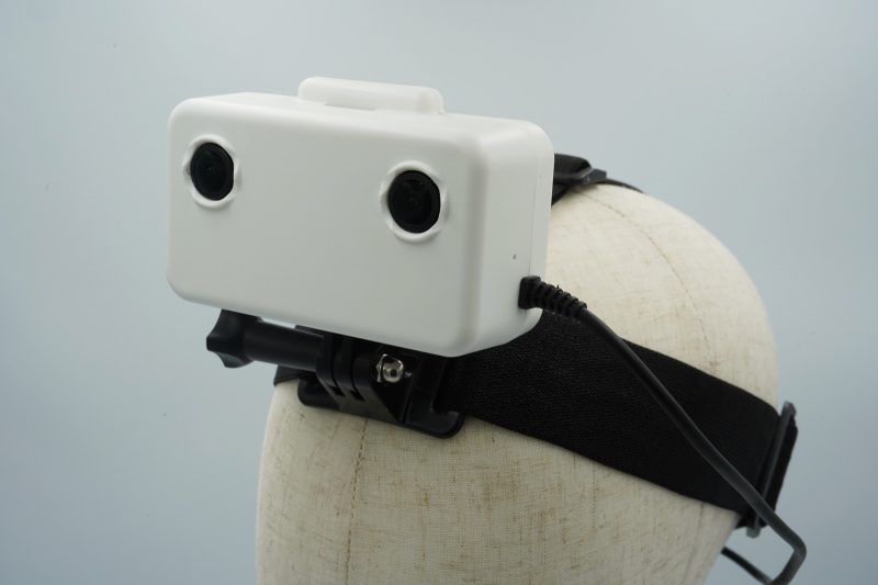
- Cameras
- 2× 1080p, 30 fps, colourMaker ↗︎
- Shutter
- RollingMaker ↗︎
- Field of view
- Calibrated ~122° × 68°Measured
120° × 72°, fisheyeMaker ↗︎ - Baseline
- 63 mmMaker ↗︎
- IMU
- 9-DoF, 200 HzMaker ↗︎
- Output
- One .mcap file, H.265Maker ↗︎
Maker values checked 2026-11-03 · 1 recording, 30.1 s · CC BY-NC 4.0 · ~ marks a value read past where the board corners reached. Past the fit: the edge lies beyond where the lens fit holds, so we give no value.
Demo and values
Section titled “Demo and values”One 30-second recording of an AprilGrid, solved with MVIS for camera, IMU and time offsets, with the rolling-shutter readout estimated too.
Reprojection is how far, in pixels, the detected corners lie from where the solve puts them. td is the camera–IMU time offset, and the lever arm is the camera–IMU position offset.
One recording, with no independent reference. These values show what MVIS solved, not how close they are to the truth.
Calibration process
Section titled “Calibration process”The path of the rig around the board, as MVIS solved it. To explore it:
- Press Play or drag the bar to follow the path.
- Use the view buttons to change the view.
- Pick a camera card to put that camera on the frustum, the pyramid that shows its view.
Each card draws the board from the solved pose, with the corners MVIS detected. We publish no camera images.
Solved rig
Section titled “Solved rig”The solved rig in 3D, to scale. Tap a sensor to see its values. In full screen you can rotate and zoom. Grid squares are 20 mm.
To scale, from above and the front
| Camera | Lever x, y, z (mm) | Distance (mm) | log(R) (rad) | td (ms) | Field of view |
|---|---|---|---|---|---|
| cam0 | −12.7, −21.3, −20.2 | 31.9 | [+0.023, −3.125, −0.021] | +55.55 | ~122° × 68° |
| cam1 | +49.4, −20.4, −21.8 | 57.8 | [+0.022, −3.117, −0.008] | +55.63 | ~128° × 68° |
Solved by MVIS. Lever arms (camera–IMU position offsets) are in the IMU frame. Rotation is log(R), camera in the IMU frame.
Specifications
Section titled “Specifications”| Measured in these recordings | |
|---|---|
| Shutter | Rolling, readout about 26 ms (solved) |
| Cameras | 2 × 1920×1080 at about 30 fps |
| Calibrated field of view | cam0 ~122° × 68° · cam1 ~128° × 68° |
| Published by the maker | |
| Field of view | 120° × 72° |
| IMU | 200 Hz, 9-DoF |
| Not published | |
| Open | Sensor part numbers |
Dataset
Section titled “Dataset”| Recording | 2026-07-17, 30.1 s |
| Format | MCAP, H.265 |
| Frames | Everything except the board is blurred |
| Frames kept at decode | cam0 889 of 900, cam1 about 859 |
| Board | AprilGrid 6×6, tag 35.2 mm, spacing 0.3 |
| Bags, configs and results | Calibench community, gi-ego1/ (access by automatic approval) |
| Licence | CC BY-NC 4.0, for the data and for this page's clip and figures; commercial use by request |
| Hosted | Calibench, gilabs-examples/ (access by automatic approval) |
Detailed results
Section titled “Detailed results”Lens Calibrated field of view
Calibrated field of view, horizontal × vertical. cam0: ~122° × 68°, corners reach 44° from the axis · cam1: ~128° × 68°, corners reach 50° from the axis
cam0 cam1
We read these from the calibrated lens fit at the image edges, through the principal point (where the optical axis meets the image). ~ marks an axis past where the corners reached, so the fit is extrapolated there. Past the fit means an edge lies beyond where the fit holds, so we give no value.
IMU Gyro–accel time offset t_ga −5.66 ms
Each bar shows a scale as its deviation from 1. IMU model: calyx. t_ga, the time offset between the gyroscope and accelerometer channels: −5.66 ± 0.64 ms.
Timing cam0 td +55.55 ms
The time offsets, to scale. td is the camera–IMU time offset, with t_imu = t_cam + td.
Full results Every solved parameter
Rotation is log(R) in rad, camera in the IMU frame.
| Parameter | MVIS |
|---|---|
| cam0 | |
| fx px | 917.21 |
| fy px | 917.02 |
| cx px | 959.66 |
| cy px | 565.21 |
| k1 | −0.02889 |
| k2 | −0.00898 |
| k3 | −0.01316 |
| k4 | 0.03078 |
| Lever x mm | −12.67 |
| Lever y mm | −21.28 |
| Lever z mm | −20.16 |
| log(R) rad | [+0.0228, −3.1248, −0.0213] |
| td ms | +55.545 |
| Reprojection px | 0.194 |
| Readout ms | −26.48 |
| cam1 | |
| fx px | 922.97 |
| fy px | 922.72 |
| cx px | 894.01 |
| cy px | 561.58 |
| k1 | −0.03227 |
| k2 | −0.00100 |
| k3 | 0.00497 |
| k4 | −0.01177 |
| Lever x mm | +49.43 |
| Lever y mm | −20.45 |
| Lever z mm | −21.78 |
| log(R) rad | [+0.0220, −3.1169, −0.0083] |
| td ms | +55.631 |
| Reprojection px | 0.198 |
| Readout ms | −26.53 |
| IMU | |
| t_ga ms | −5.66 ± 0.64 |
Limits
Section titled “Limits”- One recording, with no independent reference. These values show what MVIS solved, not how close they are to the truth.
- Gyro scale solves 3 to 4 % below 1 on all axes. We have not confirmed the cause.
How it was run
Section titled “How it was run”- Recording converted to EuRoC layout, camera-only solve per camera, then camera + IMU with camera intrinsics free, t_ga and the rolling-shutter readout both estimated. Batch of 2026-11-03.
- sha256 of the recording:
f4443fc201d70088a28aa2011c1f82597ae911f2896745bdf267fa043f8aeae4