
Hampo stereo module
Stereo colour camera with an IMU, recording to a memory card
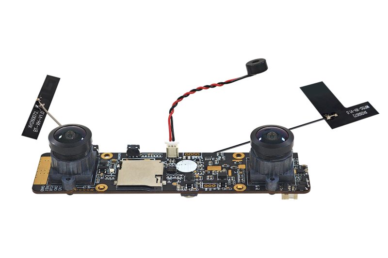
- Cameras
- 2 × 1600×1200, H.264, 30 fps, colourMeasured
- Shutter
- Not confirmed on this unitNot published
- Field of view
- Calibrated ~154° × 121°Measured
- Baseline
- 65.3 mmMeasured
- IMU
- 505 HzMeasured
- Output
- MP4 + IMU fileMeasured
Values measured in this recording · Data on Hugging Face · ~ marks a value read past where the board corners reached. Past the fit: the edge lies beyond where the lens fit holds, so we give no value.
Demo and values
Section titled “Demo and values”Stereo fisheye colour module from Dongguan Hampo Electronic Technology (翰普), with an IMU at about 500 Hz. One recording, solved as stereo and as cam0 alone.
Reprojection is how far, in pixels, the detected corners lie from where the solve puts them. td is the camera–IMU time offset, and the lever arm is the camera–IMU position offset.
No independent reference, so this shows consistency between the two solves, not accuracy.
Calibration process
Section titled “Calibration process”The path of the rig around the board, as MVIS solved it. To explore it:
- Press Play or drag the bar to follow the path.
- Use the view buttons to change the view.
- Pick a camera card to put that camera on the frustum, the pyramid that shows its view.
Each card draws the board from the solved pose, with the corners MVIS detected. We publish no camera images.
Solved rig
Section titled “Solved rig”The solved rig in 3D, to scale. Tap a sensor to see its values. In full screen you can rotate and zoom. Grid squares are 20 mm.
To scale, from above and the front
| Camera | Lever x, y, z (mm) | Distance (mm) | log(R) (rad) | td (ms) | Field of view |
|---|---|---|---|---|---|
| cam0 | −31.4, −0.7, +14.2 | 34.5 | [+0.004, −0.001, +0.002] | −4.74 | ~154° × 121° |
| cam1 | +33.9, −0.5, +14.3 | 36.8 | [+0.006, +0.003, +0.002] | −4.45 | ~153° × 120° |
| Camera | Lever x, y, z (mm) | Distance (mm) | log(R) (rad) | td (ms) | Field of view |
|---|---|---|---|---|---|
| cam0 | −32.0, −0.7, +13.7 | 34.8 | [+0.003, −0.001, +0.002] | −4.74 | ~154° × 121° |
Solved by MVIS. Lever arms (camera–IMU position offsets) are in the IMU frame. Rotation is log(R), camera in the IMU frame.
Specifications
Section titled “Specifications”| Maker | |
|---|---|
| Maker | Dongguan Hampo Electronic Technology |
| Published by the maker | |
| Closest published model | USB-3372-V1.0: dual 2MP global shutter, M12 fixed focus, IMU at 100, 200 or 500 Hz, SD storage. The exact model isn't confirmed |
| Measured in these recordings | |
| Cameras | 2 × 1600×1200, H.264, 30 fps, colour |
| IMU | 505 Hz measured, 500 Hz set |
| Sync | Both cameras share one frame time in the recorder log |
| Calibrated field of view | cam0 ~154° × 121° · cam1 ~153° × 120° |
| Not published | |
| Open | Shutter: Not confirmed on this unit; global on the USB-3372 sheet |
Sales contact Provided by the maker
| Name | 周宇华, sales manager |
| cannychow@dghpdz.cn | |
| Office phone | +86 769 8798 9852 |
Dataset
Section titled “Dataset”| Recordings | 1 recording. cam0 107.8 s, 3,235 frames. cam1 stops at 57.6 s, 1,728 frames |
| Format | Unfinalised MP4s, rebuilt, then converted to EuRoC layout |
| Board | AprilGrid 8×6, tag 50 mm, spacing 0.3 |
| Licence | CC BY-NC 4.0; commercial use by request |
| Hosted | Calibench community, hampo/ (access by automatic approval) |
Detailed results
Section titled “Detailed results”Lens Calibrated field of view
Calibrated field of view, horizontal × vertical. cam0: ~154° × 121°, corners reach 72° from the axis · cam1: ~153° × 120°, corners reach 69° from the axis
Calibrated field of view, horizontal × vertical. cam0: ~154° × 121°, corners reach 72° from the axis
cam0 cam1
We read these from the calibrated lens fit at the image edges, through the principal point (where the optical axis meets the image). ~ marks an axis past where the corners reached, so the fit is extrapolated there. Past the fit means an edge lies beyond where the fit holds, so we give no value.
IMU Gyro–accel time offset t_ga +0.03 ms
Each bar shows a scale as its deviation from 1. IMU model: calyx. t_ga, the time offset between the gyroscope and accelerometer channels: +0.03 ± 0.98 ms.
Each bar shows a scale as its deviation from 1. IMU model: calyx. t_ga, the time offset between the gyroscope and accelerometer channels: +0.04 ± 1.04 ms.
Timing cam0 td −4.74 ms
The time offsets, to scale. td is the camera–IMU time offset, with t_imu = t_cam + td.
Full results Every solved parameter
Rotation is log(R) in rad, camera in the IMU frame.
| Parameter | MVIS |
|---|---|
| cam0 | |
| fx px | 529.59 |
| fy px | 529.52 |
| cx px | 837.44 |
| cy px | 625.32 |
| k1 | 0.05578 |
| k2 | 0.00630 |
| k3 | 0.00289 |
| k4 | −0.00114 |
| Lever x mm | −31.41 |
| Lever y mm | −0.69 |
| Lever z mm | +14.20 |
| log(R) rad | [+0.0036, −0.0014, +0.0022] |
| td ms | −4.742 |
| Reprojection px | 0.444 |
| cam1 | |
| fx px | 532.83 |
| fy px | 532.78 |
| cx px | 840.58 |
| cy px | 606.22 |
| k1 | 0.05472 |
| k2 | 0.00480 |
| k3 | 0.00547 |
| k4 | −0.00184 |
| Lever x mm | +33.88 |
| Lever y mm | −0.50 |
| Lever z mm | +14.29 |
| log(R) rad | [+0.0058, +0.0031, +0.0022] |
| td ms | −4.448 |
| Reprojection px | 0.536 |
| IMU | |
| t_ga ms | +0.03 ± 0.98 |
| Parameter | MVIS |
|---|---|
| cam0 | |
| fx px | 529.56 |
| fy px | 529.47 |
| cx px | 837.67 |
| cy px | 625.27 |
| k1 | 0.05614 |
| k2 | 0.00552 |
| k3 | 0.00363 |
| k4 | −0.00137 |
| Lever x mm | −32.00 |
| Lever y mm | −0.73 |
| Lever z mm | +13.73 |
| log(R) rad | [+0.0029, −0.0008, +0.0025] |
| td ms | −4.740 |
| Reprojection px | 0.430 |
| IMU | |
| t_ga ms | +0.04 ± 1.04 |
Limits
Section titled “Limits”- No independent reference, so this shows consistency between the two solves, not accuracy.
- The recording is H.264 and the USB-3372 sheet lists MJPG and YUY2, so the exact model stays open.
- Frame stamps fall about 5.2 ms after mid-exposure, so td here isn't a physical delay.
How it was run
Section titled “How it was run”- cam0 at 30 Hz, cam1 at 10 Hz, default IMU noise, t_ga estimated, camera intrinsics free. Batch of 2026-11-03.