
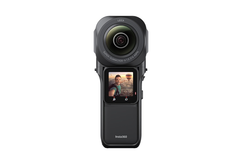
Insta360 ONE RS 1-Inch 360 Edition
360° camera: two back-to-back rolling-shutter fisheye lenses with a 1 kHz IMU
- Cameras
- 2 × 1472×1440 at 30 Hz in the recordingsDataset
- Shutter
- RollingDataset
- Field of view
- Calibrated 188° × 182°Measured
About 200° per lensDataset - Baseline
- 36.2 mmMeasured
- IMU
- 6-axis, 1 kHzDataset
- Output
- Video with embedded IMU data; ROS 2 bag in the datasetDataset
Values measured in the Hilti-Trimble SLAM Challenge 2026 calibration recordings · 2 recordings, put together as one rig · CC BY-NC-SA 3.0 data
Demo and values
Section titled “Demo and values”Consumer 360° camera from Insta360 with two 1-inch sensors behind back-to-back fisheye lenses of about 200° each and a built-in IMU at 1 kHz. It is the camera of the Hilti-Trimble SLAM Challenge 2026 dataset. Each lens is solved with the IMU from the organisers' own calibration recording, using only the part where the camera turns about all three axes, with the rolling-shutter readout and the shape of the calibration board estimated. The first tab puts the two solves together as one rig.
Reprojection is how far, in pixels, the detected corners lie from where the solve puts them. td is the camera–IMU time offset, and the lever arm is the camera–IMU position offset.
The tab with both lenses is put together from two solves, not one joint solve: each lens is placed in the IMU frame by its own recording. Its IMU values and its calibration-process view are those of the front-lens recording.
Calibration process
Section titled “Calibration process”The path of the rig around the board, as MVIS solved it. To explore it:
- Press Play or drag the bar to follow the path.
- Use the view buttons to change the view.
- Pick a camera card to put that camera on the frustum, the pyramid that shows its view.
Each card draws the board from the solved pose, with the corners MVIS detected. We publish no camera images.
Solved rig
Section titled “Solved rig”The solved rig in 3D, to scale. Tap a sensor to see its values. In full screen you can rotate and zoom. Grid squares are 20 mm.
To scale, from above and the front
| Camera | Lever x, y, z (mm) | Distance (mm) | log(R) (rad) | td (ms) | Field of view |
|---|---|---|---|---|---|
| cam0 | −14.8, −12.4, +23.5 | 30.4 | [+1.224, +1.195, −1.204] | −20.93 | 188° × 182° |
| cam1 | −15.0, +23.7, +20.5 | 34.7 | [−1.214, −1.197, −1.217] | −21.08 | 187° × 182° |
| Camera | Lever x, y, z (mm) | Distance (mm) | log(R) (rad) | td (ms) | Field of view |
|---|---|---|---|---|---|
| cam0 | −14.8, −12.4, +23.5 | 30.4 | [+1.224, +1.195, −1.204] | −20.93 | 188° × 182° |
| Camera | Lever x, y, z (mm) | Distance (mm) | log(R) (rad) | td (ms) | Field of view |
|---|---|---|---|---|---|
| cam0 | −15.0, +23.7, +20.5 | 34.7 | [−1.214, −1.197, −1.217] | −21.08 | 187° × 182° |
Solved by MVIS. Lever arms (camera–IMU position offsets) are in the IMU frame. Rotation is log(R), camera in the IMU frame.
Specifications
Section titled “Specifications”| Published by the maker | |
|---|---|
| Maker | Insta360 (Arashi Vision), lenses co-engineered with Leica |
| Image sensors | 2 × 1-inch CMOS |
| Maker video modes | Up to 6K 360° video (5888×2944 at 30 fps) |
| From the dataset | |
| Lenses | Leica Super-Summicron-A, f/2.2, 6.52 mm (35 mm equivalent); about 200° each, back to back |
| Shutter | Rolling; the two shutters are synchronised |
| Readout time | 31.05 ms, top to bottom, in the organisers' SLAM settings; 31.1 ms (front) and 31.4 ms (back) solved here |
| Measured in these recordings | |
| Images in the recordings | 2 × 1472×1440 at 30 Hz, JPEG |
| IMU | 6-axis, 1 kHz, read from the video metadata |
| Calibrated field of view | cam0 188° × 182° · cam1 187° × 182° |
Dataset
Section titled “Dataset”| Recordings | 2 camera + IMU recordings, one per lens: 233 s and 208 s, hand-held in front of the board. 1 camera-pair recording, 205 s, camera still and board moved |
| Source | Hilti-Trimble SLAM Challenge 2026 dataset (Hilti, Trimble, University of Oxford) |
| Format | ROS 2 bag (sqlite3), read directly |
| Boards | AprilGrid 7×12, tag 150 mm, spacing 0.25 (camera + IMU). AprilGrid 6×6, tag 80 mm, spacing 0.3 (camera pair) |
| Licence | CC BY-NC-SA 3.0 |
| Hosted | Not hosted here; download from the challenge dataset |
| Data | Hilti-Trimble SLAM Challenge 2026: camera_calibration |
Detailed results
Section titled “Detailed results”Lens Calibrated field of view
Calibrated field of view, horizontal × vertical. cam0: 188° × 182°, corners reach 95° from the axis · cam1: 187° × 182°, corners reach 98° from the axis
Calibrated field of view, horizontal × vertical. cam0: 188° × 182°, corners reach 95° from the axis
Calibrated field of view, horizontal × vertical. cam0: 187° × 182°, corners reach 98° from the axis
cam0 cam1
We read these from the calibrated lens fit at the image edges, through the principal point (where the optical axis meets the image). ~ marks an axis past where the corners reached, so the fit is extrapolated there. Past the fit means an edge lies beyond where the fit holds, so we give no value.
IMU Gyro–accel time offset t_ga −0.04 ms
Each bar shows a scale as its deviation from 1. IMU model: calyx. t_ga, the time offset between the gyroscope and accelerometer channels: −0.04 ± 0.08 ms.
Each bar shows a scale as its deviation from 1. IMU model: calyx. t_ga, the time offset between the gyroscope and accelerometer channels: −0.04 ± 0.08 ms.
Each bar shows a scale as its deviation from 1. IMU model: calyx. t_ga, the time offset between the gyroscope and accelerometer channels: −0.33 ± 0.07 ms.
Timing cam0 td, first row −20.93 ms
The time offsets, to scale. td is the camera–IMU time offset, with t_imu = t_cam + td. For a rolling-shutter camera td is the time of the first image row; the middle row is td + readout / 2, which is what a global-shutter calibration reports.
Board shape peak to peak 12.2 mm
The calibration board isn't perfectly flat, so this solve estimated the height of every corner off the flat board along with the calibration. The board's mean plane and tilt belong to its pose, so a flat board shows only noise here.
Full results Every solved parameter
Rotation is log(R) in rad, camera in the IMU frame.
| Parameter | MVIS |
|---|---|
| cam0 | |
| fx px | 467.25 |
| fy px | 466.61 |
| cx px | 733.17 |
| cy px | 719.64 |
| alpha | 0.69365 |
| beta | 0.88778 |
| Lever x mm | −14.80 |
| Lever y mm | −12.36 |
| Lever z mm | +23.50 |
| log(R) rad | [+1.2236, +1.1948, −1.2044] |
| td ms | −20.928 |
| Reprojection px | 0.613 |
| Readout ms | +31.05 |
| cam1 | |
| fx px | 467.49 |
| fy px | 466.77 |
| cx px | 734.13 |
| cy px | 719.48 |
| alpha | 0.69361 |
| beta | 0.88784 |
| Lever x mm | −15.01 |
| Lever y mm | +23.74 |
| Lever z mm | +20.46 |
| log(R) rad | [−1.2142, −1.1974, −1.2169] |
| td ms | −21.080 |
| Reprojection px | 0.681 |
| Readout ms | +31.30 |
| IMU | |
| t_ga ms | −0.04 ± 0.08 |
| Parameter | MVIS |
|---|---|
| cam0 | |
| fx px | 467.25 |
| fy px | 466.61 |
| cx px | 733.17 |
| cy px | 719.64 |
| alpha | 0.69365 |
| beta | 0.88778 |
| Lever x mm | −14.80 |
| Lever y mm | −12.36 |
| Lever z mm | +23.50 |
| log(R) rad | [+1.2236, +1.1948, −1.2044] |
| td ms | −20.928 |
| Reprojection px | 0.613 |
| Readout ms | +31.05 |
| IMU | |
| t_ga ms | −0.04 ± 0.08 |
| Parameter | MVIS |
|---|---|
| cam0 | |
| fx px | 467.49 |
| fy px | 466.77 |
| cx px | 734.13 |
| cy px | 719.48 |
| alpha | 0.69361 |
| beta | 0.88784 |
| Lever x mm | −15.01 |
| Lever y mm | +23.74 |
| Lever z mm | +20.46 |
| log(R) rad | [−1.2142, −1.1974, −1.2169] |
| td ms | −21.080 |
| Reprojection px | 0.681 |
| Readout ms | +31.30 |
| IMU | |
| t_ga ms | −0.33 ± 0.07 |
Limits
Section titled “Limits”- The tab with both lenses is put together from two solves, not one joint solve: each lens is placed in the IMU frame by its own recording. Its IMU values and its calibration-process view are those of the front-lens recording.
- The distance between the lenses, 36.2 mm here, comes from two camera-to-IMU results, not from one joint solve. It agrees with a direct estimate from the camera-pair recording without the IMU (36–37 mm) and with four 60 s windows (34.6–38.0 mm). The organisers' Kalibr chain gives 40.1 mm. Using the whole recordings, including the first 100–130 s where the camera turns about one axis only, gives about 34 mm; that difference isn't fully explained.
- The 7×12 calibration board isn't flat: it bows about 12 mm across its 2.2 m width, the same in both recordings. Treating it as flat moves each lens by up to 10 mm, so the board shape is estimated here; see Board shape.
- The organisers publish a Kalibr calibration (EUCM model, IMU intrinsics fixed). It isn't an independent reference: it comes from the same recordings.
- The board reaches about 95° from the lens axis, so the outermost part of each 200° image is extrapolated.
- The images are JPEG-compressed, which can shift detected corners slightly.
How it was run
Section titled “How it was run”- Each lens alone with the IMU, then both placed in the one IMU frame. Only the well-excited part of each recording is used: the camera turns about all three axes from 130 s (front) and 100 s (back), and the last 10 s, where it is put down, are left out; 92 s and 97 s. Camera intrinsics (enhanced unified model, EUCM, as in the organisers' calibration) start from a single-camera solve and stay free; the shape of the 7×12 board, rolling-shutter readout, camera time offset, IMU scale and misalignment and the gyro-to-accel offset t_ga are estimated. IMU noise measured on the camera-pair recording, where the camera stands still, and widened about 2.8×. Solved 2026-11-12.