
CyperStereo four-camera module
Four-camera global-shutter RGB module with a 6-axis IMU
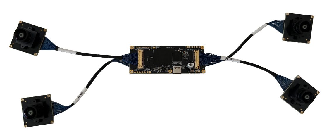
- Cameras
- 4 × 1280×1024 RGBMeasured
- Shutter
- GlobalMaker ↗︎
- Field of view
- Calibrated 131° × 110°Measured
160° and 200° diagonalMaker ↗︎ - Baseline
- 66.6 mmMeasured
- IMU
- Bosch BMI088, 200 HzMeasured
- Output
- USB 3.0 / UVC, ROS bagMeasured
Values measured in this recording · Maker values from the CyperStereo product manual, read 2026-11-11
Demo and values
Section titled “Demo and values”Four-camera inertial module from Shenzhen Tujian Intelligent Technology (图间智能). Four global-shutter RGB cameras sit on separate 25 × 25 mm boards, cabled to one controller with a Bosch BMI088 IMU; two cameras have 160° lenses and two have 200° lenses, and the baseline is set by how the boards are mounted. One recording, solved as four cameras + IMU.
Reprojection is how far, in pixels, the detected corners lie from where the solve puts them. td is the camera–IMU time offset, and the lever arm is the camera–IMU position offset.
No independent reference, so these values show what MVIS solved, not how close they are to the truth.
Calibration process
Section titled “Calibration process”The path of the rig around the board, as MVIS solved it. To explore it:
- Press Play or drag the bar to follow the path.
- Use the view buttons to change the view.
- Pick a camera card to put that camera on the frustum, the pyramid that shows its view.
Each card draws the board from the solved pose, with the corners MVIS detected. We publish no camera images.
Solved rig
Section titled “Solved rig”The solved rig in 3D, to scale. Tap a sensor to see its values. In full screen you can rotate and zoom. Grid squares are 20 mm.
To scale, from above and the front
| Camera | Lever x, y, z (mm) | Distance (mm) | log(R) (rad) | td (ms) | Field of view |
|---|---|---|---|---|---|
| cam0 | +52.9, +13.4, +24.3 | 59.7 | [−0.016, −1.583, −2.710] | +0.80 | 131° × 110° |
| cam1 | −13.7, +12.7, +24.6 | 30.9 | [−0.002, −1.579, −2.711] | +0.80 | 131° × 110° |
| cam2 | +85.5, +2.1, +15.6 | 87.0 | [+0.515, +1.958, +1.908] | +0.79 | 170° × 137° |
| cam3 | −47.1, +0.1, +16.0 | 49.7 | [+0.523, −1.937, −1.918] | +0.80 | ~171° × 137° |
Solved by MVIS. Lever arms (camera–IMU position offsets) are in the IMU frame. Rotation is log(R), camera in the IMU frame.
Specifications
Section titled “Specifications”| Published by the maker | |
|---|---|
| Maker | Shenzhen Tujian Intelligent Technology (深圳市图间智能科技有限公司) |
| Image sensor | SmartSens SC136HGS, RGB, global shutter, back-illuminated, 4 × 4 µm pixels |
| Wide lenses (cam2, cam3) | 1.67 mm, F2.0, M12; 200° diagonal, 174° × 139° |
| Narrow lenses (cam0, cam1) | 1.79 mm, F2.0, M12; 160° diagonal, 133° × 112° |
| Synchronization | Camera to camera 10 µs, camera to IMU 100 µs on the sheet; identical camera stamps in this recording |
| Link and power | USB 3.0, UVC; 1.5–2 W at 5 V |
| Measured in these recordings | |
| Cameras | 4 × 1280×1024; 30 fps on the sheet, 15 Hz in this recording |
| IMU | Bosch BMI088, 200 Hz |
| Calibrated field of view | cam0 131° × 110° · cam1 131° × 110° · cam2 170° × 137° · cam3 ~171° × 137° |
Sales contact Provided by the maker
| support@tujian.com |
Dataset
Section titled “Dataset”| Recordings | 1 recording, 74.6 s, hand-held. About 1,120 frames per camera, 14,920 IMU samples |
| Format | ROS1 bag |
| Board | AprilGrid 6×6, tag 55 mm, spacing 0.3 |
| Licence | None |
| Hosted | Not hosted |
Detailed results
Section titled “Detailed results”Lens Calibrated field of view
Calibrated field of view, horizontal × vertical. cam0: 131° × 110°, corners reach 77° from the axis · cam1: 131° × 110°, corners reach 77° from the axis · cam2: 170° × 137°, corners reach 86° from the axis · cam3: ~171° × 137°, corners reach 87° from the axis
cam0 cam1 cam2 cam3
We read these from the calibrated lens fit at the image edges, through the principal point (where the optical axis meets the image). ~ marks an axis past where the corners reached, so the fit is extrapolated there. Past the fit means an edge lies beyond where the fit holds, so we give no value.
IMU Gyro–accel time offset t_ga −4.36 ms
Each bar shows a scale as its deviation from 1. IMU model: calyx. t_ga, the time offset between the gyroscope and accelerometer channels: −4.36 ± 0.12 ms.
Timing cam0 td +0.80 ms
The time offsets, to scale. td is the camera–IMU time offset, with t_imu = t_cam + td.
Full results Every solved parameter
Rotation is log(R) in rad, camera in the IMU frame.
| Parameter | MVIS |
|---|---|
| cam0 | |
| fx px | 449.26 |
| fy px | 449.82 |
| cx px | 657.09 |
| cy px | 526.38 |
| k1 | 0.23203 |
| k2 | −0.01098 |
| k3 | −0.02659 |
| k4 | 0.00821 |
| Lever x mm | +52.88 |
| Lever y mm | +13.36 |
| Lever z mm | +24.26 |
| log(R) rad | [−0.0159, −1.5832, −2.7104] |
| td ms | +0.800 |
| Reprojection px | 0.621 |
| cam1 | |
| fx px | 450.41 |
| fy px | 450.48 |
| cx px | 636.48 |
| cy px | 518.24 |
| k1 | 0.22978 |
| k2 | −0.00836 |
| k3 | −0.02944 |
| k4 | 0.00910 |
| Lever x mm | −13.68 |
| Lever y mm | +12.74 |
| Lever z mm | +24.63 |
| log(R) rad | [−0.0015, −1.5789, −2.7113] |
| td ms | +0.804 |
| Reprojection px | 0.643 |
| cam2 | |
| fx px | 417.88 |
| fy px | 417.70 |
| cx px | 641.28 |
| cy px | 507.31 |
| k1 | 0.01399 |
| k2 | 0.01291 |
| k3 | −0.00923 |
| k4 | 0.00154 |
| Lever x mm | +85.53 |
| Lever y mm | +2.13 |
| Lever z mm | +15.56 |
| log(R) rad | [+0.5153, +1.9580, +1.9083] |
| td ms | +0.785 |
| Reprojection px | 0.398 |
| cam3 | |
| fx px | 418.82 |
| fy px | 419.14 |
| cx px | 624.83 |
| cy px | 510.81 |
| k1 | 0.01040 |
| k2 | 0.01466 |
| k3 | −0.00990 |
| k4 | 0.00161 |
| Lever x mm | −47.06 |
| Lever y mm | +0.11 |
| Lever z mm | +15.97 |
| log(R) rad | [+0.5227, −1.9369, −1.9176] |
| td ms | +0.803 |
| Reprojection px | 0.416 |
| IMU | |
| t_ga ms | −4.36 ± 0.12 |
Limits
Section titled “Limits”- No independent reference, so these values show what MVIS solved, not how close they are to the truth.
- The board never reached the outer side of the two 200° images (about two-thirds of each image is covered), so the lens model there is extrapolated.
- The IMU noise set for the solve is wider than the residuals need (IMU χ²/dof 0.03); a solve with tighter noise is still to do.
- The tag size is taken from the target file sent with the data and isn't confirmed on the printed board. It scales every baseline and lever arm.
How it was run
Section titled “How it was run”- All four cameras and the IMU together. Camera intrinsics (Kannala–Brandt kb4) from four single-camera solves of the same recording, then held fixed; IMU scale and misalignment, gyro-to-accel offset t_ga and camera time offsets estimated. IMU noise from the BMI088 datasheet, about 2.5× wider. Solved 2026-11-11.