
- Cameras
- 848 × 480 here: IR stereo + RGBMeasured
- Shutter
- GlobalMaker ↗︎
- Field of view
- Calibrated 89° × 58°Measured
87° × 58° depth, 90° × 65° RGBMaker ↗︎ - Baseline
- 94.4 mmMeasured
- IMU
- 6-axis, gyro 400 Hz, accel 200 HzMeasured
- Output
- USB-C, ROS bagMaker ↗︎
Maker values checked 2026-11-13 · 1 recording, 90 s · CC BY-NC 4.0
Demo and values
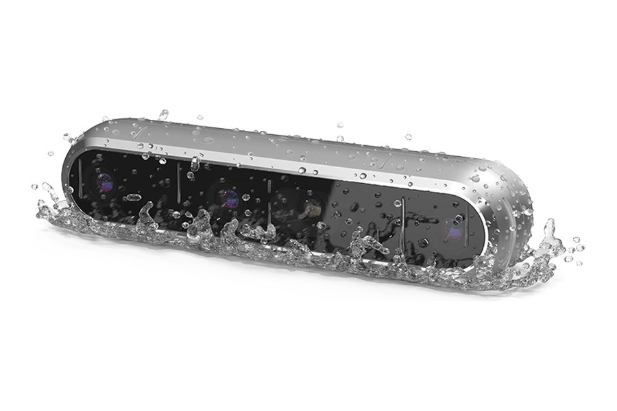
Section titled “Demo and values”Depth camera from RealSense with a 95 mm global-shutter infrared stereo pair, a global-shutter RGB camera and a 6-axis IMU in an IP65 enclosure, built on the same D450 camera module as the D455. One hand-held recording in front of a chessboard on a screen, solved as left infrared + right infrared + RGB + IMU.
Reprojection is how far, in pixels, the detected corners lie from where the solve puts them. td is the camera–IMU time offset, and the lever arm is the camera–IMU position offset.
One recording, with no independent reference on this page. These values show what MVIS solved, not how close they are to the truth.
Calibration process
Section titled “Calibration process”The path of the rig around the board, as MVIS solved it. To explore it:
- Press Play or drag the bar to follow the path.
- Use the view buttons to change the view.
- Pick a camera card to put that camera on the frustum, the pyramid that shows its view.
Each card draws the board from the solved pose, with the corners MVIS detected. We publish no camera images.
Solved rig
Section titled “Solved rig”The solved rig in 3D, to scale. Tap a sensor to see its values. In full screen you can rotate and zoom. Grid squares are 20 mm.
To scale, from above and the front
| Camera | Lever x, y, z (mm) | Distance (mm) | log(R) (rad) | td (ms) | Field of view |
|---|---|---|---|---|---|
| cam0 | −27.0, +6.8, +22.0 | 35.5 | [+0.007, +0.011, +0.006] | +7.08 | 89° × 58° |
| cam1 | +67.4, +7.4, +21.3 | 71.1 | [+0.007, +0.009, +0.006] | +7.08 | 89° × 58° |
| cam2 | +31.6, +7.0, +21.7 | 38.9 | [+0.009, +0.008, +0.005] | +6.03 | 90° × 59° |
Solved by MVIS. Lever arms (camera–IMU position offsets) are in the IMU frame. Rotation is log(R), camera in the IMU frame.
Specifications
Section titled “Specifications”| Published by the maker | |
|---|---|
| Maker | RealSense (formerly Intel RealSense) |
| Camera module | RealSense Module D450 with the Vision Processor D4 |
| Shutter | Global, on the infrared pair and the RGB camera |
| Infrared pair | 87° × 58° depth field of view, 95 mm baseline; recorded here at 848×480, 30 Hz, both images on one stamp |
| RGB camera | 1 MP, 90° × 65°, up to 1280×800 at 30 fps; recorded here at 848×480, 30 Hz |
| Enclosure | IP65: dust-tight and protected against water jets |
| Link | USB-C; 124 × 29 × 26 mm |
| Measured in these recordings | |
| IMU | 6-axis; gyro 400 Hz, accelerometer about 200 Hz in this recording |
| Calibrated field of view | cam0 89° × 58° · cam1 89° × 58° · cam2 90° × 59° |
Dataset
Section titled “Dataset”| Recording | 1 recording, 90 s, hand-held. 2,700 frames per infrared camera, 2,699 RGB frames, 36,471 IMU samples |
| Format | ROS1 bag |
| Board | Chessboard shown on a screen, 10×7 squares (9×6 inner corners), 75 mm squares as measured by the recorder |
| Exposure | Fixed, about 2 ms on all three cameras; no auto exposure |
| Data | Calibench community, realsense-d456/data/ (access by automatic approval). Everything except the chessboard is blurred. CC BY-NC 4.0, for the data, clip and figures; commercial use by request |
| Configs and results | Calibench community, realsense-d456/ (access by automatic approval) |
Detailed results
Section titled “Detailed results”Lens Calibrated field of view
Calibrated field of view, horizontal × vertical. cam0: 89° × 58°, corners reach 47° from the axis · cam1: 89° × 58°, corners reach 47° from the axis · cam2: 90° × 59°, corners reach 48° from the axis
cam0 cam1 cam2
We read these from the calibrated lens fit at the image edges, through the principal point (where the optical axis meets the image). ~ marks an axis past where the corners reached, so the fit is extrapolated there. Past the fit means an edge lies beyond where the fit holds, so we give no value.
IMU Gyro–accel time offset t_ga −4.89 ms
Each bar shows a scale as its deviation from 1. IMU model: calyx. t_ga, the time offset between the gyroscope and accelerometer channels: −4.89 ± 0.27 ms.
Timing cam0 td +7.08 ms
The time offsets, to scale. td is the camera–IMU time offset, with t_imu = t_cam + td.
Full results Every solved parameter
Rotation is log(R) in rad, camera in the IMU frame.
| Parameter | MVIS |
|---|---|
| cam0 | |
| fx px | 429.63 |
| fy px | 430.04 |
| cx px | 426.80 |
| cy px | 241.14 |
| k1 | −0.00188 |
| k2 | −0.00180 |
| k3 | 0.00020 |
| k4 | 0.00141 |
| Lever x mm | −27.04 |
| Lever y mm | +6.84 |
| Lever z mm | +21.97 |
| log(R) rad | [+0.0072, +0.0108, +0.0059] |
| td ms | +7.083 |
| Reprojection px | 0.105 |
| cam1 | |
| fx px | 429.39 |
| fy px | 429.81 |
| cx px | 426.78 |
| cy px | 241.39 |
| k1 | −0.00098 |
| k2 | −0.00203 |
| k3 | 0.00041 |
| k4 | 0.00094 |
| Lever x mm | +67.38 |
| Lever y mm | +7.43 |
| Lever z mm | +21.33 |
| log(R) rad | [+0.0069, +0.0090, +0.0059] |
| td ms | +7.084 |
| Reprojection px | 0.085 |
| cam2 | |
| fx px | 426.73 |
| fy px | 426.57 |
| cx px | 429.41 |
| cy px | 246.78 |
| k1 | −0.05057 |
| k2 | 0.03740 |
| k3 | 0.00024 |
| k4 | 0.00203 |
| Lever x mm | +31.58 |
| Lever y mm | +6.97 |
| Lever z mm | +21.66 |
| log(R) rad | [+0.0092, +0.0078, +0.0050] |
| td ms | +6.025 |
| Reprojection px | 0.099 |
| IMU | |
| t_ga ms | −4.89 ± 0.27 |
Limits
Section titled “Limits”- One recording, with no independent reference on this page. These values show what MVIS solved, not how close they are to the truth.
- The square size, 75 mm, is the recorder's measurement of the board shown on a screen, and it scales every baseline and lever arm. The solved stereo baseline is about 0.7 % under the 95 mm the maker lists.
- The infrared images are the camera's own rectified output, so their distortion is close to zero by construction and the values describe that output, not the bare lens.
- The recorder turned the camera's IMU correction off, so the IMU scale and bias values are those of the raw sensor. The accelerometer was resampled onto the gyro's time stamps before the solve.
How it was run
Section titled “How it was run”- Left infrared, right infrared and RGB cameras with the IMU in one solve, all three treated as global shutter. Pinhole camera with radial-tangential distortion, seeded from three single-camera solves of the same recording and left free; camera time offsets, IMU scale and misalignment and the gyro-to-accel offset t_ga estimated. The board is kept rigid. IMU noise is the MVIS default, since no measured values exist for this unit. Solved 2026-11-13.