
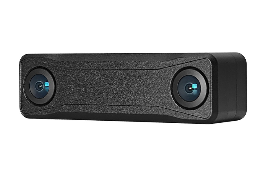
ALG AVS115D-Y stereo module
GMSL2 rolling-shutter stereo camera module with a 6-axis IMU
- Cameras
- 2 × 1920×1920Measured
- Shutter
- RollingMaker ↗︎
- Field of view
- Calibrated ~118° × 118°Measured
119° × 119°Maker ↗︎ - Baseline
- 65.5 mmMeasured
- IMU
- ICM-45686, 200 Hz hereMeasured
- Output
- GMSL2, ROS2 bagMeasured
Values measured in the 163 s and 101 s recordings · Maker values from the AVS115D-Y product page, read 2026-11-14 · CC BY-NC 4.0 · ~ marks a value read past where the board corners reached. Past the fit: the edge lies beyond where the lens fit holds, so we give no value.
Demo and values
Section titled “Demo and values”GMSL2 stereo camera module from Shenzhen Aili-Light Technology (ALG Tech, 艾利光), with two 1920×1920 rolling-shutter cameras 65 mm apart and a 6-axis IMU. Two hand-held recordings in front of a ChArUco board, the second in stronger light with a much shorter exposure, each solved as stereo + IMU with each camera's readout time estimated.
Reprojection is how far, in pixels, the detected corners lie from where the solve puts them. td is the camera–IMU time offset, and the lever arm is the camera–IMU position offset.
No independent reference on this page. These values show what MVIS solved, not how close they are to the truth. The two recordings agree within 1.4 mm on the lever arm, 0.15 % on the gyro scales, 0.8 ms on the readout and 0.1 mm on the baseline.
Calibration process
Section titled “Calibration process”The path of the rig around the board, as MVIS solved it. To explore it:
- Press Play or drag the bar to follow the path.
- Use the view buttons to change the view.
- Pick a camera card to put that camera on the frustum, the pyramid that shows its view.
Each card draws the board from the solved pose, with the corners MVIS detected. We publish no camera images.
Solved rig
Section titled “Solved rig”The solved rig in 3D, to scale. Tap a sensor to see its values. In full screen you can rotate and zoom. Grid squares are 20 mm.
To scale, from above and the front
| Camera | Lever x, y, z (mm) | Distance (mm) | log(R) (rad) | td (ms) | Field of view |
|---|---|---|---|---|---|
| cam0 | +33.0, −7.6, +15.1 | 37.0 | [−0.015, −0.003, −3.140] | −14.29 | ~118° × 118° |
| cam1 | −32.5, −7.8, +15.8 | 37.0 | [+0.006, +0.005, +3.141] | −14.43 | 119° × 118° |
| Camera | Lever x, y, z (mm) | Distance (mm) | log(R) (rad) | td (ms) | Field of view |
|---|---|---|---|---|---|
| cam0 | +33.3, −6.2, +16.5 | 37.7 | [−0.014, −0.016, −3.141] | −1.43 | 119° × 119° |
| cam1 | −32.1, −6.4, +17.2 | 36.9 | [+0.005, +0.019, +3.140] | −1.53 | 118° × 118° |
Solved by MVIS. Lever arms (camera–IMU position offsets) are in the IMU frame. Rotation is log(R), camera in the IMU frame.
Specifications
Section titled “Specifications”| Published by the maker | |
|---|---|
| Maker | Shenzhen Aili-Light Technology (ALG Tech) |
| Model | AVS115D-Y, 1920×1920 at 30 fps (AVS115D-B06-M95DFA1-RABI) |
| Image sensor | 1/2.7-inch CMOS, 2.0 µm pixels, rolling shutter |
| Lens | 1.90 mm, 119° × 119° |
| IMU | TDK ICM-45686 (named by ALG), 6-axis, up to 6400 Hz on the sheet; 200 Hz in both recordings |
| Link and power | GMSL2, power over coax, 9 to 12 V, 2.3 W |
| Measured in these recordings | |
| Cameras | 2 × 1920×1920, 30 Hz with no dropped frames in either recording; left and right stamps 5 µs apart (median) |
| Calibrated field of view | cam0 ~118° × 118° · cam1 119° × 118° |
Sales contact Provided by the maker
| sales@aili-light.com | |
| Phone | +86 755 2721 8150 |
Dataset
Section titled “Dataset”| Recordings | 2 hand-held recordings. Recording 1 (2026-11-13): 163 s, cam0 4,900 frames, cam1 4,899, IMU 32,664 samples. Recording 2 (2026-11-14, stronger light, shorter exposure): 101 s, 3,024 frames per camera, IMU 20,164 samples |
| Format | ROS2 bag with compressed images, converted to EuRoC layout |
| Board | ChArUco 14×9 squares, 40 mm squares, 30 mm markers |
| Data | Calibench community, alg-avs115d/data/ (access by automatic approval). Both recordings, every frame, normal frames: alg_avs115d_01.bag is recording 1 and alg_avs115d_02.bag recording 2, with the IMU already corrected for the accel 4× and gyro 2× scale; the blurred pairs left out of each solve are listed next to its bag. Recorded by ALG Tech and hosted with their permission. CC BY-NC 4.0, for the data, clip and figures; commercial use by request |
| Configs and results | Calibench community, alg-avs115d/ (access by automatic approval) |
Detailed results
Section titled “Detailed results”Lens Calibrated field of view
Calibrated field of view, horizontal × vertical. cam0: ~118° × 118°, corners reach 60° from the axis · cam1: 119° × 118°, corners reach 63° from the axis
Calibrated field of view, horizontal × vertical. cam0: 119° × 119°, corners reach 70° from the axis · cam1: 118° × 118°, corners reach 71° from the axis
cam0 cam1
We read these from the calibrated lens fit at the image edges, through the principal point (where the optical axis meets the image). ~ marks an axis past where the corners reached, so the fit is extrapolated there. Past the fit means an edge lies beyond where the fit holds, so we give no value.
IMU Gyro–accel time offset t_ga +0.96 msGyro–accel time offset t_ga +1.08 ms
Each bar shows a scale as its deviation from 1. IMU model: calyx. t_ga, the time offset between the gyroscope and accelerometer channels: +0.96 ± 0.16 ms.
Each bar shows a scale as its deviation from 1. IMU model: calyx. t_ga, the time offset between the gyroscope and accelerometer channels: +1.08 ± 0.20 ms.
Timing cam0 td, first row −14.29 mscam0 td, first row −1.43 ms
The time offsets, to scale. td is the camera–IMU time offset, with t_imu = t_cam + td. For a rolling-shutter camera td is the time of the first image row; the middle row is td + readout / 2, which is what a global-shutter calibration reports.
Full results Every solved parameter
Rotation is log(R) in rad, camera in the IMU frame.
| Parameter | MVIS |
|---|---|
| cam0 | |
| fx px | 953.28 |
| fy px | 953.43 |
| cx px | 948.79 |
| cy px | 958.01 |
| k1 | −0.01454 |
| k2 | −0.01968 |
| k3 | 0.02142 |
| k4 | −0.01036 |
| Lever x mm | +32.97 |
| Lever y mm | −7.58 |
| Lever z mm | +15.10 |
| log(R) rad | [−0.0147, −0.0027, −3.1401] |
| td ms | −14.288 |
| Reprojection px | 0.240 |
| Readout ms | +31.09 |
| cam1 | |
| fx px | 953.19 |
| fy px | 953.35 |
| cx px | 961.33 |
| cy px | 955.48 |
| k1 | −0.01769 |
| k2 | −0.00811 |
| k3 | 0.00362 |
| k4 | −0.00178 |
| Lever x mm | −32.52 |
| Lever y mm | −7.81 |
| Lever z mm | +15.84 |
| log(R) rad | [+0.0056, +0.0055, +3.1413] |
| td ms | −14.432 |
| Reprojection px | 0.257 |
| Readout ms | +31.41 |
| IMU | |
| t_ga ms | +0.96 ± 0.16 |
| Parameter | MVIS |
|---|---|
| cam0 | |
| fx px | 952.37 |
| fy px | 952.35 |
| cx px | 949.20 |
| cy px | 958.50 |
| k1 | −0.01700 |
| k2 | −0.00971 |
| k3 | 0.00483 |
| k4 | −0.00168 |
| Lever x mm | +33.31 |
| Lever y mm | −6.16 |
| Lever z mm | +16.54 |
| log(R) rad | [−0.0139, −0.0158, −3.1410] |
| td ms | −1.432 |
| Reprojection px | 0.209 |
| Readout ms | +31.92 |
| cam1 | |
| fx px | 952.31 |
| fy px | 952.24 |
| cx px | 961.54 |
| cy px | 955.72 |
| k1 | −0.01818 |
| k2 | −0.00826 |
| k3 | 0.00584 |
| k4 | −0.00244 |
| Lever x mm | −32.07 |
| Lever y mm | −6.36 |
| Lever z mm | +17.20 |
| log(R) rad | [+0.0047, +0.0192, +3.1403] |
| td ms | −1.527 |
| Reprojection px | 0.208 |
| Readout ms | +32.10 |
| IMU | |
| t_ga ms | +1.08 ± 0.20 |
Limits
Section titled “Limits”- No independent reference on this page. These values show what MVIS solved, not how close they are to the truth. The two recordings agree within 1.4 mm on the lever arm, 0.15 % on the gyro scales, 0.8 ms on the readout and 0.1 mm on the baseline.
- The camera-only solve, without the IMU, puts the readout at 25 ms (recording 1) and 21 ms (recording 2) against 31–32 ms here; the board's motion alone pins it less well, so the joint value is the one shown.
- In a simulated copy of recording 1, with noise matched to this unit, MVIS recovered the lever arm within 1.2 mm, the rotation within 0.3 mrad, the time offset within 0.5 ms, the readout within 0.6 ms and the gyro scales within 0.7 %. With MVIS's default IMU noise the same test drifts (lever arm 6 mm along the optical axis, gyro scales 1 to 1.6 %), which is why this solve uses the tighter noise.
- The camera–IMU time offset differs between the recordings: td is −14.3 ms in recording 1 and −1.4 ms in recording 2, each ± 0.1 ms, while everything else repeats. The likely cause is the exposure time. The driver stamps each image a fixed 45 ms before it reaches the host in both bags, so the stamp follows the readout. td refers to the middle of the first row's exposure, which comes before the readout by half the exposure time: a longer exposure moves it earlier and makes td more negative.
- The bags don't record the exposure time. Measured from the motion blur, recording 1 was exposed for about 18 to 21 ms and recording 2 for about 2 to 5 ms. Half of that change is about 8 ms: the right direction, but short of the 13 ms measured, and the rest is still open. On the Dibuli Prism A4L, two exposures 1 ms apart moved td by 0.5 to 0.7 ms per ms of exposure, close to what this explanation predicts.
- In practice, td on this module depends on the exposure, so with auto-exposure it is not one number. Stamp frames at mid-exposure if the driver allows it, or use the td measured at an exposure close to yours; recording 2's value suits short exposures.
How it was run
Section titled “How it was run”- Both cameras and the IMU, rolling shutter with each camera's readout time estimated, Kannala–Brandt (kb4) lenses with intrinsics free, IMU noise set about 5× tighter than MVIS's default to match this unit, t_ga estimated. Fast motion blurred some frames; stereo pairs whose board edges were more than 1.5× wider than the median were left out (17 % of the pairs in recording 1, 0.6 % in recording 2). The IMU stored accel 4× and gyro 2× too small; both were scaled before solving. Solved 2026-11-14 (recording 1) and 2026-11-15 (recording 2), with the same settings.